Mission Communications was first to use the digital control channel of the cellular network for monitoring, control, databasing, and automated alarm/status notification for fixed base assets in North America.
Mission-managed SCADA is a turnkey system delivered through a Software as a Service (SaaS) model that enables customers to gain complete system monitoring. Mission provides and maintains everything customers need to control their system.
With current wireless technology, the only constant is change. Mission customers can always take advantage of the latest hardware and wireless network breakthroughs with generous trade-in and upgrade policies
Mission does not just manufacture hardware but also supplies the tools that provide customers with management information concerning their remote facilities and the people that maintain those facilities. The hardware simply gathers the information. Mission is continually upgrading its centralized management information services, which are immediately available via the Internet to all customers.
Mission is committed to maintaining total customer satisfaction by providing the highest quality remote monitoring equipment and notification services, utilizing the most cost-effective wireless transport technology, and exceeding customer expectations.
The choice to focus on the water and wastewater industries allows Mission to listen to customer suggestions and develop an intuitive and highly reliable service.
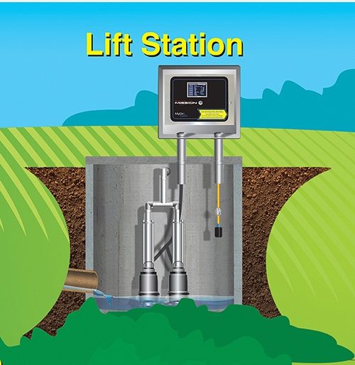
Lift Station
Mission RTUs are Engineered for Lift Stations
The M110 and MyDro M150 are appropriate for monitoring most duplex lift stations. Two digital inputs (DIs) are typically used to monitor pump runtimes and starts. Another DI is used for high-level float monitoring and alarming purposes. The other DIs are available for items like phase fault, seal fail, or hatch door.
The M800 or MyDro 850 RTU is appropriate at master lift or pump stations, where real-time level information (every two minutes or 5% change) or other analog trending is desired. Additional insight of the master lift stations is available with real-time pump state changes on up to 8 pumps. This additional information allows additional flow reporting as described below.
Graphs of Daily/Hourly Pump Runtimes and Starts
Automatically collect, post, graph, and chart runtimes and starts. MyDro 150 and the M110 will collect up to three pump runtimes and starts, while the MyDro 850 and the M800 will take up to eight. Both systems will also track and report simultaneous runtimes in duplex lift stations as well as automatically notify users if a pump exceeds an adjustable hourly starts threshold.
Automated Pump Problem Analysis of Daily Runtimes
The Mission system can alert users of pump anomalies before they turn into expensive alarm conditions. Save time by letting Mission software catch pumps that aren’t running in their normal variance parameters, and automatically alert plant management in a separate notification list.
Estimated Flow Calculations
The MyDro 150 and the M110 estimate flow by multiplying runtimes by the gallons per minute (GPM) rating of each pump.
More accurate flow calculations are available with Mydro 850 and M800 RTUs via the volumetric flow calculation method. With a one-time entry of the sump surface area, the Mission system is able to calculate the volume of liquid that is pumped each pump cycle. Either the analog level reading or fixed heights are used in the algorithm. The flow calculation is made even more accurate by estimating inflows during the cycle.
While users can connect a pulse or analog flow meter to a MyDro 850 or the M800 and have it report and graph instantaneous or integrated flow, the volumetric method is nearly as accurate, and much easier to implement.
RTU-to-RTU Automatic Control of Upstream Lift Stations
The MyDro 850 and the M800 RTUs will detect a high wet well level, send users an alarm and automatically call upstream lift stations to shut down or divert their pumps until the high level clears. Remote manual control of pumps or gates is also possible.
Integrated Site Activity Logs
From its inception, Mission has used electronic keys to track who is checking in and out of field sites. This allows management to maintain CMOM audit trails without resorting to soggy or illegible paper sheets kept at each station.
Don’t Pay For More Than is Necessary
Using traditional SCADA for the complex process control and large input/output needs that frequently occur in-plant makes sense but that level of complexity is probably unnecessarily complicated for simple lift stations and master pump stations.
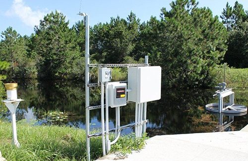
Rainfall Monitoring
Rainfall History in Real-Time
Mission remote terminal units (RTUs) can connect to industry-standard rainfall tipping buckets and report rainfall totals. Monitor rainfall events and totals in real-time and gain precious minutes to prepare for floods and avoid spills. Graph rainfall on a daily, weekly, or monthly basis to analyze wet weather events in great detail. Rainfall data can be exported to Excel spread sheets, CSV files, or can be fed into existing SCADA systems via the Mission OPC software link.
Place Rain Gauges Where They are Needed
The ultra-reliable cellular data links will work across the block or county, so users can position rain gauges anywhere. Some customers have placed rain gauge stations over 100 miles from their home location.
Compare With Pump Runtimes and Flows for I & I Studies
Before utilities spend hundreds of thousands, if not millions, on sewer lines or plant capacity, long-term data on inflow and infiltration (I&I) is necessary. The Mission system helps users compare rainfall data from government sources or their own rain gauges with pump station runtimes or flow meter data. Mission supplies long-term graphing tools and many of these graphs can be implemented in user reports.
Standalone or Integrated Packages
Position rain gauges at selected lift stations for just a few more dollars to gain alarms, runtimes, starts, and rain data—all from the same unit. If users need to monitor just rainfall, Mission supplies a complete rain gauge station which includes:
Stand
Leveling plate
Rain gauge
Solar cell

OPC-UA
Secure, Service-Oriented Architecture to Connect Mission Data to Plant Operations
Managers of larger wastewater treatment or water processing facilities sometimes prefer the data collected by Mission to be included with the client/server SCADA HMI that is part of their plant operations. Mission has provided this service to customers via the Open Platform Communications (OPC) Classic connection method for more than 10 years. In 2016, Mission released the newest connection method known as the OPC-Unified Architecture (UA). The Mission OPC-UA connection is based on the latest standard (v 1.03) from the OPC Foundation. No Mission software is required on-site because the OPC-UA server runs remotely within the secure Mission infrastructure.
What is OPC-UA?
OPC-UA is an industrial communication protocol developed for process control and is the successor to the OPC Classic protocol. It offers better security, stability, and software support with added features like multi-platform support. OPC-UA simplifies connections because it no longer depends on legacy Microsoft COM/DCOM technologies. The new protocol also makes firewall client-side configurations much easier.
What can it do?
Up to 240 data points per remote terminal unit (RTU) (based on RTU configuration) are sent to a SCADA-HMI once an OPC-UA connection is established. These include:
Digital inputs—labels and state
Digital outputs—(relay outputs) labels and state
Analog input—labels, absolute values, and scaled values
Hourly and daily information such as pump run, number of pump starts, flows, and rainfall information
Battery and AC voltage
Count of unacknowledged alarms
Many more enhancements
RTU data is continuously stored on the Mission data servers so the Mission web portal is always available for viewing, configuration, and other functions. Some OPC customers use Mission for telemetry and their SCADA-HMI for alarming and reporting. Others take a hybrid approach where alarm call-outs and acknowledgments are performed by Mission and their traditional system tracks history. Other managers use Mission as a backup system and only enable Mission alarm call-out functions when they are needed.
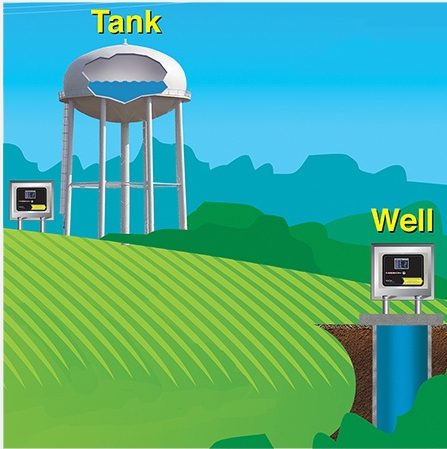
Tank and Well
Remote Control for Water Systems
The Tank and Well system maintains the water level in storage tanks by automatically sending commands that signal remote well or booster pumps to turn on and off. The system relies on either a MyDro 850 or M800 remote terminal unit (RTU) and a transducer to measure the tank level. There are no radio networks, computers, or PLCs to maintain. It is low-cost and easy to set up.
How It Works
The RTU at the water tank transmits level information to Mission servers. When the tank level is outside the user configurable level boundaries, a command is automatically sent to output relays on the same RTU or remote RTUs to energize pumps or valves and refill the tank. The Tank and Well software supports up to five pumps. RTUs may be connected to additional equipment such as chlorine monitors or other alarm inputs and can be solar powered.
Real-time alarms notify operators of high or low tank levels, excessive pump starts, excessive pump runtimes, AC failure, low battery, and more. Positive relay feedback business logic can notify users to conditions such as “pump called to run but failed to run.” A situation like this could be the result of a burned-out pump or a tripped breaker.
The web portal allows an operator with appropriate security credentials to adjust the pump on/off trigger levels and view current level readings. Trending graphs and reports are accessible on desktops and web-enabled devices such as desktop computers, smartphones, and tablets.
Optimization and Money Saving Features
The software includes an optional pump alternator feature which cycles through each well pump connected to a Tank and Well system. It can also be set up to evenly distribute pump runtimes across all wells or alternate the lead pump to favor the well that has had the least water production in the last one to seven days.
Maximum runtimes can be set for each pump, and the system will alternate to the next pump once the maximum runtime is reached. This reduces the risk of damaging the water table by over-pumping.
The off-peak force fill feature saves money by filling the tank when electricity rates are lower than peak hour rates.
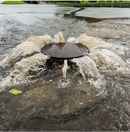
CSO/SSO
In-Sewer Wireless Alarm System
The wireless Mission SCADA system can also work below ground in a sewer system to detect and report sewer surcharges and floods. Use the Mission Manhole Monitor to provide a waterproof CSO/SSO tracking and alarm system that mounts in a sewer just below the manhole lid. The enclosure houses all electronics, radio, and battery—yet is only about the size of a paperback book.
Two sewer floats attach via waterproof connectors to signal when the sewer is surcharging and when levels get to flood stage. The Manhole Monitor will instantly transmit these alarms via the ultra-reliable cellular network to Mission servers. Phone calls, pages, faxes, or emails notify utility personnel of the alarm.
A clear message will describe the alarm, the unit name, and the location. This gives utility crews time to proactively mitigate the problem. All alarm records can be accessed via the secure customer website. Now users can easily report when the surcharge started and stopped.
Five+ Year Battery
The Manhole Monitor was built with the sewer environment in mind:
Rugged, metal enclosure that is robust and serviceable
Electronics are designed for use in Class 1, Division 2, Groups 3 & 4 hazardous environments
The Manhole Monitor is rated to last more than five years on its internal batteries with no expensive site visits to maintain the system
The Manhole Monitor automatically checks in once daily and reports cellular system health and battery voltages